Spooks 5 window Ford project.

A few bits to keep the updates succinct and regular.
I took the original engine mounts and brackets in to work this week as one rubber mount had been cut off and the top cap was seized into the aluminium bracket. It took some doing but finally it came free. I'd ordered some new rubber doughnuts off eBay but the only trouble I had was that the studs on the new mounts were M10 where the old mounts were M12. The other issue was that the studs on the new rubbers were only 20mm long. That meant that the stud would only poke out of the mount about 2mm to try and get a nut on. Unacceptable.
As the brackets were corroded anyway I decided the best course of action was to drill them out, tap them and then make an insert adaptor to pick up the new M10 threads.

This is one of the new mounting rubbers:
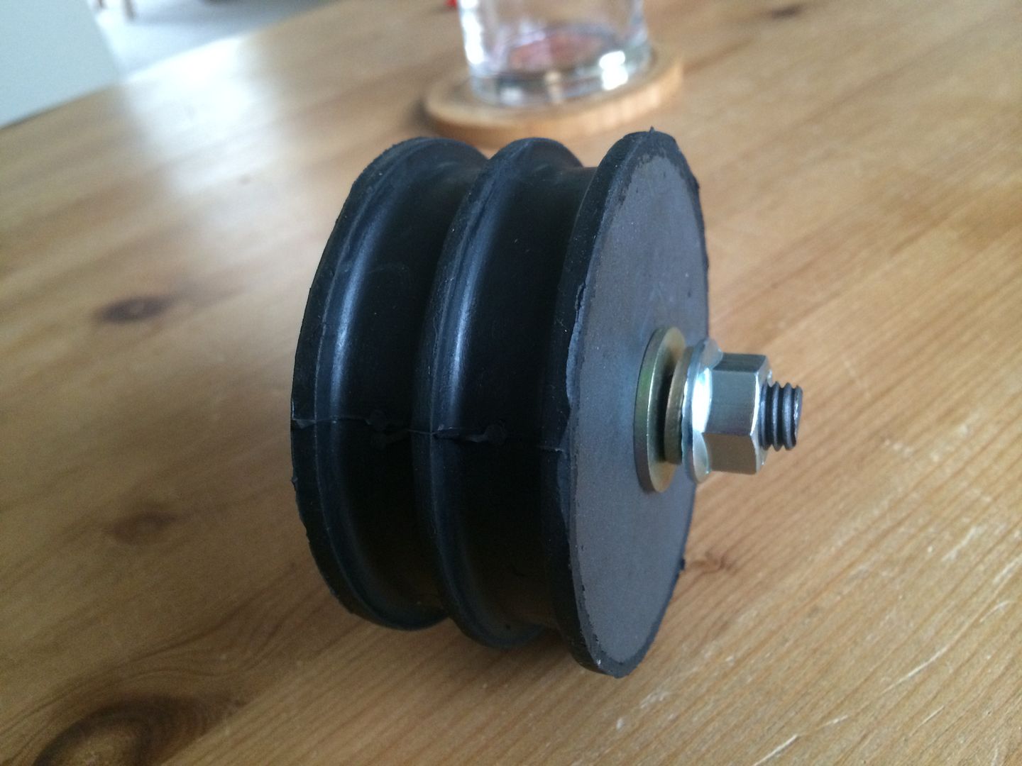
483A0069-0F28-4DA4-9095-F9EB6BDCE08F.jpg


These are the old brackets that I've de-seamed and sanded down to remove the corrosion. You can also see the new mounts that will be welded to the frame rails:

28B4F5AD-FFAC-45A0-A937-EE80D88901F5.jpg


This is an M16 tapped hole to accept the new adaptor:

8E96F954-4580-4403-8101-DD45B126B191.jpg


This is the adaptor I made today:

E597410E-8C96-4475-93A0-B61F12AACDB4.jpg


It's M16 outside thread and M10 down the middle. This will be screwed to the underside of the bracket up to the flange and glued in so basically the bracket and adaptor will become one component. The rubber mounts will then be screwed into that and fitted as a whole. The other end stud will then go through the frame brackets and have a nut and spring washer put on.
I'll be getting the other adaptor done tomorrow and then I can remount the brackets and get the frame mounts tacked into place.
I need to pick up another bottle of gas for the welder before then though as someone left it on (definitely me).

I also had my rear coilovers arrive today. I'm not sure if they're man enough yet but they will drop the frame at least 90mm so even if they do for mock-up then that's fine. £32 delivered. They are an eye mount both ends so if anyone has any ideas on cars that have this set up and cheaply available coilies then I'm open to suggestions.

These are they anyway. Shiny!:

9BC5A039-7288-4E74-86D9-8BFE1D297CC8.jpg


They look super weedy there but there will be significantly less weight at the back than there would have been originally.
I'll update tomorrow if I get the motor mounted.
 
Not the most productive day today but some small things achieved.
So I got up early this morning to get into work and finish of the last few jobs on the motor mounts.
I had one adaptor ready to go so I test fitted it in the mount to give me an idea of what it all looked like together:

227B154C-43C4-480C-9149-4737058C6BC6_1.jpg


32835CFD-5A33-444E-84FC-9B29763FFEF6.jpg


I was pretty happy with the fitment so I made another one and then fitted the rubber mounts to complete the assembly.

0560CA1D-2917-4E8B-9709-85EA469DDD58_1.jpg


70A455E2-DCFA-433E-A6F8-FB6BFC96F49C.jpg


So this is the whole conversion kit for putting a 1UZ-FE into a Reliant Scimitar chassis with a '32 Ford body shell. They should sell hundreds!
The welder was out of gas and the place that sells refills was shut so that was where my day ended with regards to the project.
I'll be getting more gas this week so I should have this buttoned up by Friday afternoon weather permitting.
 
Decent update time.
I had my welding gas delivered today so I had run out of excuses not to sort the engine mounts out.
After bit of time getting the new wire and gas in the welder I uncovered the chassis and cleared the area of anything flammable.
Once my work area was free I could crack on with mocking up the motor mounts. The plan was to have the 'L' shaped brackets welded to the inside of the chassis rails. As I started fiddling around with getting everything level and square I realised that I had to rethink that idea. The new rubber mounts are around 80mm in diameter. This meant that they would overlap the chassis rails. Also the mounts were a bit wider than I remember so they were too close for the slots in the new brackets to line up.
What I decided was to cut the return flange off and just use the slotted side as a plate on top of the frame. This allowed me to set the width of the slots and also made a bit of an easier welding job as it's laying on top.
I could measure up to the front suspension turrets both sides and back from the frame edge so that they both sat parallel and square with each other.
After I ha marked where they were going I hoisted the lump out of the way so I could clean up the area with my grinder. This chassis has been painted and undersealed so there was a fair amount of crap to scrape of before there was a good welding surface. Measurements double checked and then I welded them into place.

E65226C3-8E30-4E4A-B4F4-6F78014B672F.jpg


CC52BDC9-E81B-4C2C-8169-151C139D380F_1.jpg


The weld is still a bit proud of the flat face of the bracket but until I've welded in the side supports I won't worry too much about it.
The same the other side really so I didn't bother with a pic. After that little job I could set the engine back down on the frame. It took a little bit of wiggling about but it went in pretty easy.

All grounded and secure:

D4E31F98-9000-4291-AA3D-BBCD3C35DA40.jpg


I'm putting two little triangular bits in to support the weight a bit better.

The next job is to finalise the rear gearbox mounting which means I've got to work out my driveline angle for the drive shaft. It's a bit of a steep learning curve but I've seen loads of YouTube videos so what could possibly go wrong?
More coming Sunday (probably).
 
Was on Youtube yesterday and a tip from Lincoln Tech said drivelines are happiest between 5 and 8 degrees!

Love this build dude, I defo have to have a go at summat before I'm too old to care!
 
Was on Youtube yesterday and a tip from Lincoln Tech said drivelines are happiest between 5 and 8 degrees!

Love this build dude, I defo have to have a go at summat before I'm too old to care!

Are you watching Hot Rod Garage by any chance? ;)

The rear diff is lower than the gearbox and also offset to the drivers side by about 100mm. That means I've got a compound driveline angle as it's not straight in either the vertical or horizontal planes. I won't know how far off I am until I can actually get a piece of tubing in and measure off it. Not going to be straightforward but it's not insurmountable.
Fun fun fun!
 
Lol yeah, they need to get back to the old Roadkill tho.

Will be a bit tricky but surely should be fine if your angles aren't daft.
 
Lol yeah, they need to get back to the old Roadkill tho.

Will be a bit tricky but surely should be fine if your angles aren't daft.

I agree. Dodgekill was rubbish.

Working it out on paper with some rough guesses on lengths and offsets I think they'll be around 6.5 degrees in both planes, which should be ok with decent UJ's.
That being said I've still got to drop the rear by quite a lot so that will bring the diff closer to the level of the gearbox yoke which will help out with the vertical angle.
 
A few little bits done this week.
I made the centre support for the gearbox mount at work on Thursday night. It's made out of 60 x 10mm flat steel bar so it's fairly substantial and should hold up ok. The gearbox mount is rubber anyway so it should be isolated from any vibrations.

3D6988AD-64B4-461E-AF7B-66C9FFF7C837.jpg


You can just about see it here between the frame rails.

C9FC715D-F33A-4D7E-8687-5973AF884A53.jpg


The other leap forward was the issue I had with the oil filter housing. The engine needed to be lower in the frame so I had to take out the unnecessarily long filter housing to make room.

091027E8-63A6-495C-8978-6AB4F0501844.jpg


The plan was to maybe cut the casting and tap it for flexible lines. On closer inspection that would have been a bit of a nightmare to do and to make look right. I decided to make a plate to cover the hole and then tap some 1/2 BSPT holes to run the feed and return lines from. It was a bit of a bugger to measure it up but after an hour or so I had it programmed into the machine.
I managed to 'salvage' some material from some left over stock so I started with this:

15FCC8A2-ED7C-4AE1-ABAF-B92CB947D038.jpg


Put it in a machine, pressed the button and 8 minutes later I had this:

067C96EF-ABA9-4B6B-8CEA-8A838EC992B9.jpg


I've cut the recess for the original oil seal so in theory it should fit exactly as the old one. Unfortunately I ran out of time to take the back off and tap the holes but that will be done Thursday so I can get it fitted, along with some lines, and the engine filled back up with oil and rotating.
As the engine was now fully mounted and bolted in I could drop the back end on the new shocks. They are ridiculously shiny against the crusty chassis but they do actually fit, which was more luck than judgment I have to admit.
This is the first side

9A1ECAA7-E9B2-445B-A90E-B95AFC5F3AF3.jpg


I knew it had dropped a lot as I couldn't get the jack out from under the frame. A bit of faffing and measuring and I've achieved a full 3 and 3/4 inch or in English 95mm. :D So it now sits at 5 inches at it's lowest point which may lift a bit once the front end is levelled out.

6998A161-0E75-4F92-821C-21E9D5FEC385.jpg


All in all I'm quite happy with where it sits now. The driveshaft angle seems to be around 4 degrees in both planes so well within reach of running a single shaft rather than a having a coupling in the middle of two shorter shafts.
Next on the list is to get the body back over and see where that sits with the wheel, frame and top of the engine.
If the weather holds next weekend I may even get a chance to start on the floor or shell supports.
 
Last edited:
Was hoping for a vid of you driving it around the yard!

Lovely work Spook all the same, love how low those rails are, thing will look savage.
 
Ok then another little update. With the engine in the chassis and a helpful assistant in tow I thought it would be a good time to test fit the body and check clearances on the engine and new mounts. When the engine was first put onto the chassis with the body, the front cowl fouled on the top of the motor. This meant that the body couldn't be dropped anywhere near were I wanted it to. Gaining about 8 inches in clearance by mounting the Lexus lump properly in between the rails meant that there should be not such troubles this time.
The first attempt threw up another small set-back, the rear wheel wells were fouling on the 4 link bars at the rear axle so we lifted the body up enough to get in there and marked up a 6 inch radius cut on the wells.

8C95F0A6-500B-460D-A983-7CC1D8BE6407.jpg


You can just about see the green highlighter mark where I needed to cut

818A9DFE-41A1-4EC0-BB83-7957B2C07BB4.jpg


With that deftly cut free the body was able to slide even further down the frame.
Even though I still have to drop the front by about 60mm to level the frame I still think it's worthwhile to get the body on and see what it looks like.
The rear need to come up about another inch or so as the fenders are fouling on the rear wheels but at least there is enough room to work with now.

A38EFABF-D415-4722-8652-738477A6937E.jpg


A view from the rear. I'll have to really clean up the rear of the frame as it will be seen when it's on the road at this height.

BEFE3C75-E6C1-405C-A4E9-B5839A5D79D6.jpg


I put the front grill on just to give a sense of length on the front and give a level for the front cowl to line up with

B0304D4C-820B-4278-8295-FBB95B51CE44.jpg


I'll hopefully mount the grill further back than that to cover the power steering rack a bit and give the front frame rails a bit more of a standard '32 Ford profile. You can see here that the firewall will actually easily clear the rear of the engine. This is because the whole body shell has had to be moved backwards to line the wheels up with the swage lines in the wheel wells. I may make a firewall out of steel and bolt it to the chassis separate to the body as I want to mount the brake master cylinder and stuff to it and I wouldn't trust the fibreglass one that came with the body not to crack.
Next on the agenda is the set the front height of the chassis and then I can start making up the new floor out of box section and start framing out the fibreglass shell prior to fettling.
 
Last edited:
I've bought quite a few bits for this this week:
- Oil line fittings and hose
- Front suspension
- Steel box section for the frame/floor
- Wheel spacers for the rear
- Other little bits

Basically I wanted the chassis set level so I could start building the floor from a square and level base. Unfortunately I made a slight miscalculation on the front coilovers and ended up not being able to fit them.
These are they:
BEA2976C-7050-4CC7-B5EB-B85C06C988D4.jpg


I bought some stiffer springs for them so that they would be able to cope with the weight of the engine but unfortunately I bought the wrong diameter so I wasn't able to get them fitted. If they fit and function ok I will get another set for the rear.
With that out of the way I had to make a decision on the floor. The original plan was to make a floor off the chassis and make a frame for the body. The body could then be removed and the floor left in place. After a lot of thought, and the fact I couldn't build squat off a wonky chassis, I decided to build the frame and floor in one with the body. It's a much more conventional approach even with the fibreglass shell and it will save doubling up on mating sections of frame and floor to keep the overall weight down to a minimum.
On that note I freed up this afternoon to crack on with it. I had a few new toys to play with so I was quite enthusiastic.

New (to me) Cut-off saw:

F95A6FBB-D9BC-49EB-95DE-F9C279805C7C_1.jpg


Brand new pipe bender (my favourite):

48B07412-C0EB-4AD0-8ABA-9B134F9627E8.jpg


So I got set up and established my workshop for the day:

C8A23F6D-FC58-4500-86FE-3513BCFAE7B5.jpg


As you can see I just rolled the body off the chassis so I could lay some rails on the lower sill sections. These were a bit trickier than I had anticipated. They curve from front to back and also they have a little kick up in front of the doors. Anyway I took some pre-cut lengths of box section (50x25x3mm) and started to form the lower sill rails. The bender made the job really easy once I had figured out how much the work springs back once you let off. There was bout an hour or so in each rail and around 12 bends I think.

89DCB9E6-9860-4338-B641-CDC4E929FB7B.jpg


I'm pretty happy with the fit. I made sure both sections were the same curvature so the fibreglass will shape to the steel and provide a mirror image on both sides.
Here you can see the little kick in front of the door and the opposite rail laying on the floor:

15E6B051-A145-46A5-91D3-6D6B787317FB_1.jpg


Now with those in place I had a bit of a dilemma. As the body was going to sit lower than the chassis and the gearbox tunnel was in the way I couldn't simply weld a couple of flat braces in to line everything up so I had a cunning plan where I made a frame hoop for the firewall:

D362DE90-48AD-482F-8704-712DB77E7900.jpg


I kind of ran out of time and energy at this point so I have mothballed it until tomorrow when I can get a full day in. The next step is to make a hoop to fit behind the door opening and run along what would be the top front edge of the deck lid opening, which you can see in that picture as well. Once that's in place and tacked I can use that frame to set the height of the body when I get the chassis level. From there I can make the hoops for the gearbox tunnel and tie it in to some chassis mounts. I may stick the box section upright to follow the contour of the chassis rails and then just bolt straight to that underneath or lay some box on top of the rails and bolt through from inside. I'll flip that coin when the body frame is done.
I made some framework for the rear wheel well but I'm not happy with the shape so I'll be doing them again properly when I get some more 25mm square box next week.
Fail:
F1791060-D2E8-4E09-8A21-BDC4433A3990.jpg


That's it for now but there will be more tomorrow!
 
This is a delayed update from last weekend. Rain did indeed stop play on the Sunday but I managed to scrounge a bit of floor space inside and work on the frame a bit more out of the wind.
I lifted the shell of and turned it turtle once more so I could get to the sills.
Having already made 3 of the potential 4 pieces of the basic skeleton I couldn't see there being many more hours in this section...
I was wrong!
Despite being quite far ahead with the main structural members I still hadn't really run a tape measure over the shell to check it for straightness and see if it was square. Of course being fibreglass there was an element of flexibility which, to be fair, worked to my advantage. I clamped both sill rails on to the body to give me something solid and straight to work to. I then measured across the shell from corner to diagonal corner. They measured up around 35mm out of square which sounds a lot but bear in mind every millimetre you move one piece; the other comes closer by the same amount, so in real term only 17-18mm out of line.
I pulled them square and welded a brace in between the sill rails to hold them in place. From there I could weld in the front firewall hoop. I'm still not happy with this piece so I'm replacing it with a tubular piece once I get everything inline and mocked up.
I then got a better look at the rear section. The idea was to run a similar hoop up from the sills, up and under the boot opening and back down the other side. The trouble with this was that the boot opening is actually about 6-7 inches further back than the end of the sill rail. As I was getting a bit fractious I decided to use the wheel tub bars I had bent previously and scrapped to bring the mounting point back and weld in a straight bar across the lot. This frame will be completely replaced now apart from the two sill rails.

A little look at what I was up to. You can see both the front hoop and the rear cross member along with the diagonal bracing bar:

3AED2497-F4B8-4D3A-91D1-6C685DA14BB7_2.jpg


There was a lot of fitting, removing, welding, re-fitting, removing, welding... so I was quite glad when it was all stitched together. The main problem with this is that the width of the body is a lot narrower than at the waistline. This means it's a bit of a bugger to keep lifting it in and out as you have to try and walk it in from one end.

Here is a view from the front all welded up:

2F082981-8C4A-4E53-967E-CD487924F55A_1.jpg


Her it is laid out bare next to the chassis:

9AC507BA-3BDF-4D60-B6B8-5676E2CC6899.jpg


D850FFB5-0FD9-4FB4-A717-E46684C8EDF0_1.jpg


You'll notice in the above picture the mounting point for the rear 4-link suspension in front of the rear wheels. I'll come back to that...

With that bit done I could use the skeleton frame to mock up the final position of the body relative to the chassis. With all the suspension problem I had I wasn't able to level the chassis out so there wasn't much left to do other than see if everything fitted together.
I lifted the frame over the chassis and propped it up on some bricks to give an idea of finished height. There was a slight problem. I had intended the body to sit just over the chassis to give it a more traditional look where you can see the chassis under the body itself. The issue was that the sill rails extended past the mounting brackets for the 4-link rear. They are almost the same width so the best I could do was have the rails sitting underneath the mounting brackets either side. It wasn't too bad but I will most likely have to notch the rear section of the sill rails out and return that inboard to miss the moving (hopefully) suspension link bars.

85B2CD1B-D05D-409F-986B-EB239283B712.jpg


The original floor would have sat level with that mounting bracket (in fact the floor supports actually welded directly on to that point) but as I want it slightly lower I'm going to have to go round them and extend the wheel tubs inward to cover the gap.
Overall though it was a worthwhile exercise and it threw light on some of the foibles that come with building a car from scratch without any real previous experience outside of YouTube!
I ripped the old floor out and placed the body back over the frame.

This picture highlights the problem area. You obviously don't want moving suspension parts inside the cabin!:

AE074CA3-3B6B-46A9-83EE-F2A4BE00C220.jpg


Piccy from the back. The rear may end up being a bit lower than that if I can get some crazy offset rear wheels to go on, or I fabricate some out of old trailer wheels until I get her all mounted:

9AFF16C9-2F27-4AF7-81D5-30348CCB48CE.jpg


I now have the correct springs for the front so I can fit them and level the chassis at some stage in the near future. My college course is fast becoming an issue with assignment work so I think I'll probably mothball this for a few weeks until I can properly concentrate on it. Lots to do!
 
Back
Top Bottom