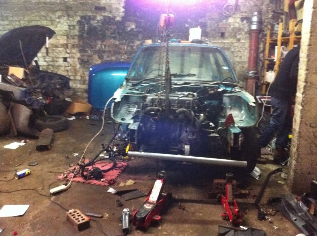
The Turtle

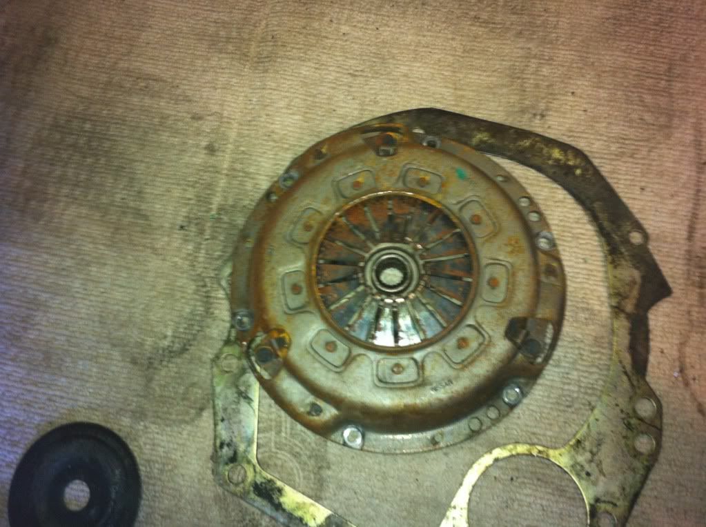
should last a while mate as there is plenty of friction material left, though one thing i noticed about it is that instead of springs in the middle it has polyurethane bushes, and it's a proper nissan one too
 
IMG_0748.jpg

Oh no, not 11 kilos!

Quick, get the forklift!
 
Think Ross is sleeping so he can add things tomorrow, but.

On tuesday we made a start on sorting out the wiring on the turtle and splicing the rear of the Micra loom (rear lights, fuel pump) into the Almera loom up front ( clocks, indicators, lights etc....)

We started off with this :
IMG_0602.jpg


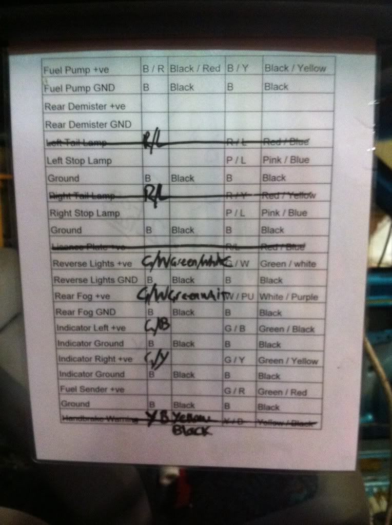
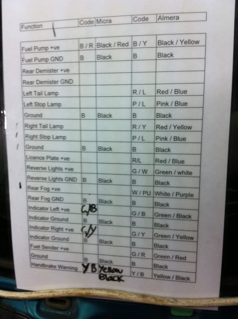
A laminated spreadsheet of wiring colours for almera and what we knew of the micra. Laminated so we could add to it as we go and change if it was wrong.
As we don't have a proper wiring diagram for the Micra, only an Italian FSM which isnt much use, we need to work out which wire is which and add it to the board.

IMG_0604.jpg


So far we have wired up what has been crossed off the list. Not amazing progress, but its a start. We have a working handbrake light?

Once all the wiring is done, it will be taken off wire by wire and each will be soldered together correctly and heat shrinked.

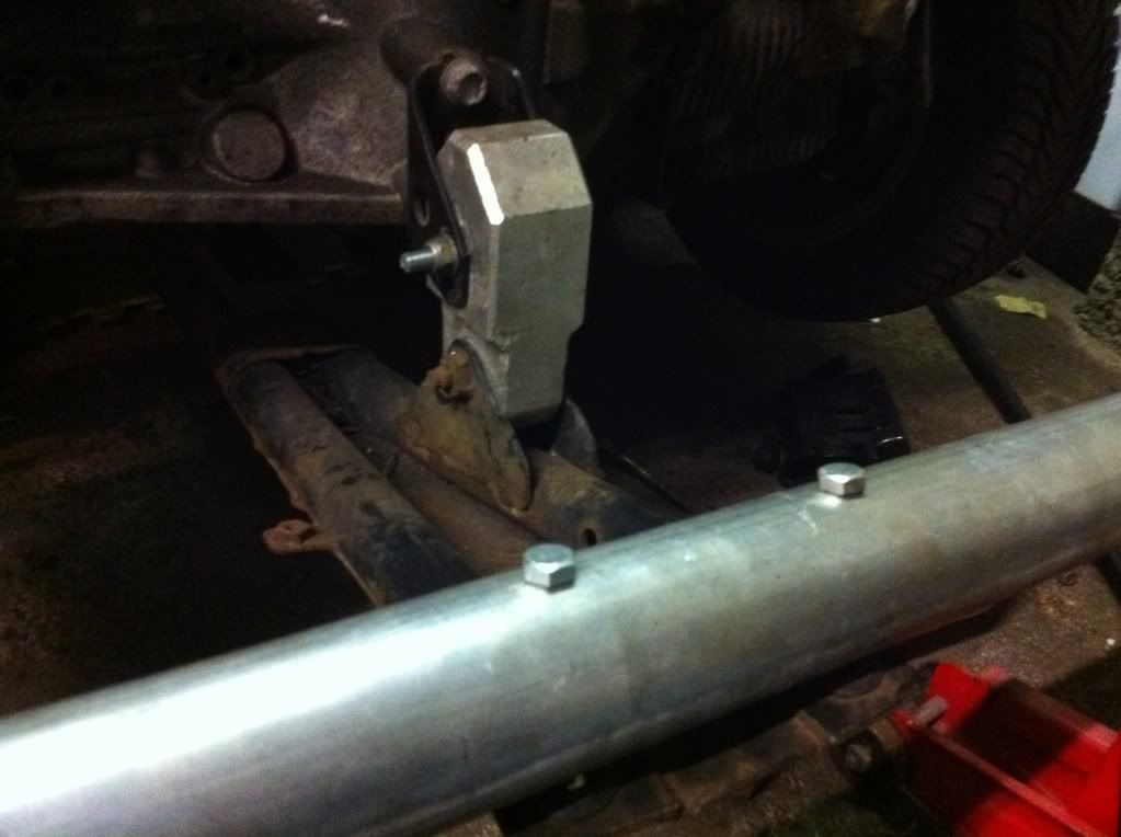
Next job was to start on the underbrace and crossmember. We have used an Almera 1.4 underbrace here with the SR20 mounts. The back 2 boltts line up pretty closely and only required the hole to be widened a small amount for the bolts to go in.

IMG_0607.jpg


You can kinda see the cut in this picture ^^^

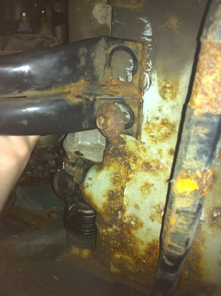
The original plan was to take the advice from Dave Bull and use the lower part of the almera crossmember and weld it onto the Micra to be able to use the front mounting holes for the engine. Unfortunatley, due to the excessive lifting on Ross's car during its many engine swaps, the crossmember has weakened, cracked and is a bit of a rusty mess.

It was then decided that if anything was to happen and the engine was to be taken out for whatever reason, it would require lifting the car off of the engine.

So to make it easier, a custom lower crossmember will be fabricated and welded onto the Micra chassis which we will then made unboltable for ease if the engine has to be taken out in the future and also it should hopefully be alot stronger than the 14 year old rusty almera one..

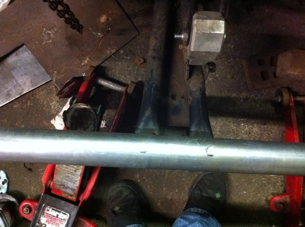
We have used 2 inch exhaust pole here. It had two holes drilled into where the underbrace will bolt into using nuts and bolts. It was then cut to size for the length of the Micra.

Pictures of crossmember progress so far...

IMG_0613.jpg

IMG_0612.jpg

IMG_0611.jpg


Thats all for now.
 
Good progress lads :thumb: Wiring and engine mounting have to be the biggest problems here and looks like it's in hand.
 
Have I misunderstood or ate you using a piece of exhaust as a structural part of the chassis? I'm not sure that is a great idea as the wall thickness of the tubing isn't thick enough to provide the strength you will need to support the engine. I'd suggest some 4" box or something of that nature purely on safety grounds. You'll only need 1.5m or so. Cost about £10 tops.
 
The mountings at the side of the engine and gearbox take the weight of the drivetrain and the front and rear mounts are catcher mounts, simply to reduce the drivetrain from rocking while under load.
 
Still semi-structural even though it's a torque mount. It's not my car so I'm not going to change anything but my advise as an automotive engineer is to replace the cross members with something of equal (or greater) strength. A nice bit of 3" or 4" box steel is goin to cost about a fiver most likely, it's stronger than the original piece, nice easy flat surface to weld to ustead of dealing with curves and the wall thickness is such that you can chuck a really decent bead if weld on it without it blowing. The end plates for mounting it will have to be fairly substantial anyway. That cross member is also there (in part) to stabalise the chassis rails as well. I'm not knocking what's already been done but I think it can be done more easily and better with the right materials.
 
Still semi-structural even though it's a torque mount. It's not my car so I'm not going to change anything but my advise as an automotive engineer is to replace the cross members with something of equal (or greater) strength. A nice bit of 3" or 4" box steel is goin to cost about a fiver most likely, it's stronger than the original piece, nice easy flat surface to weld to ustead of dealing with curves and the wall thickness is such that you can chuck a really decent bead if weld on it without it blowing. The end plates for mounting it will have to be fairly substantial anyway. That cross member is also there (in part) to stabalise the chassis rails as well. I'm not knocking what's already been done but I think it can be done more easily and better with the right materials.

The wall thickness of the tubing is thicker than the OEM metal. @1.2mm Vs 1mm, plus you have the added factor of no corrosion having weakened the steel.

All that ties the engine to this cross beam in the OEM design is 2 x M8 bolts.

the end plates will be 5mm plate bolted together with 3 x M10 bolts each end.

it will be strong enough to do all it is ever going to need to do.
 
Update :

So tonight was mainly spent on De-rusting the Turtle.

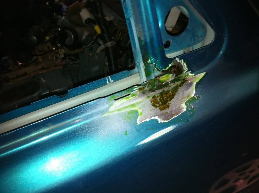
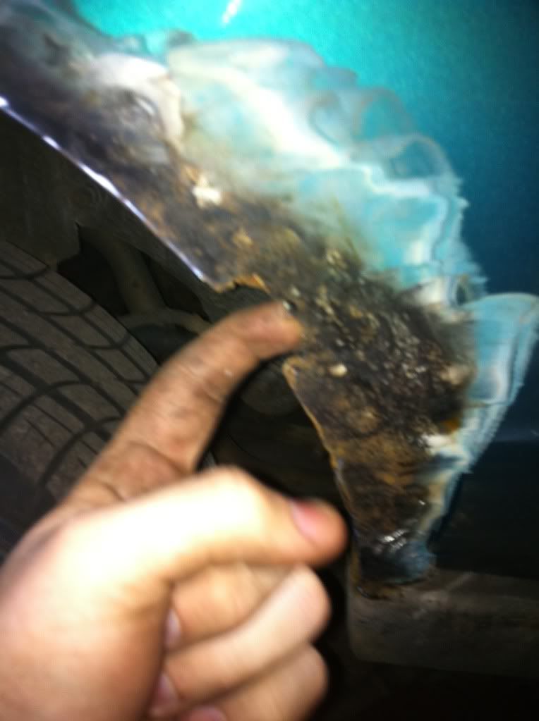
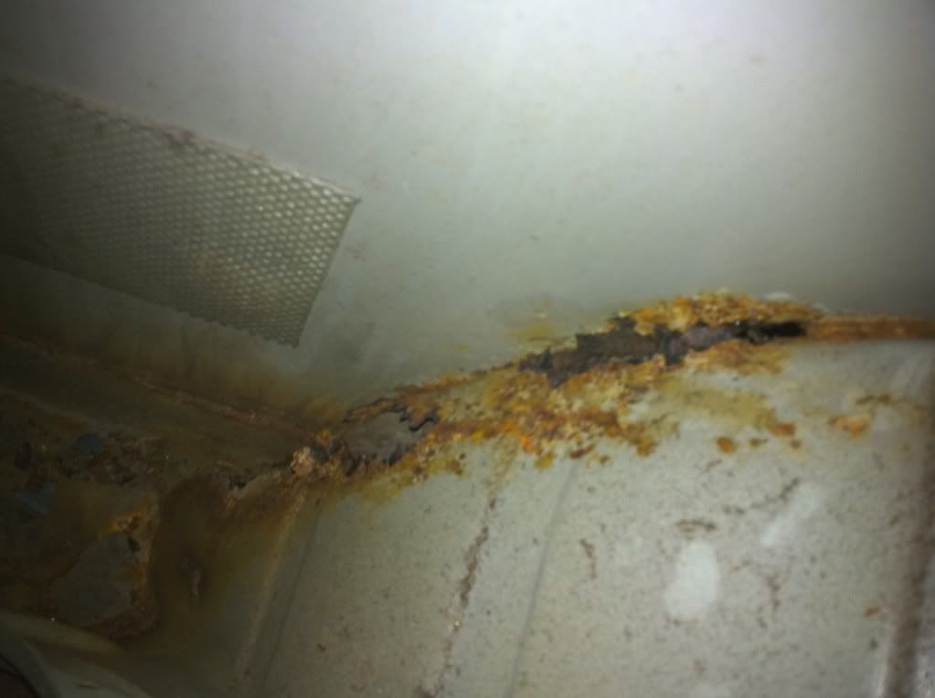
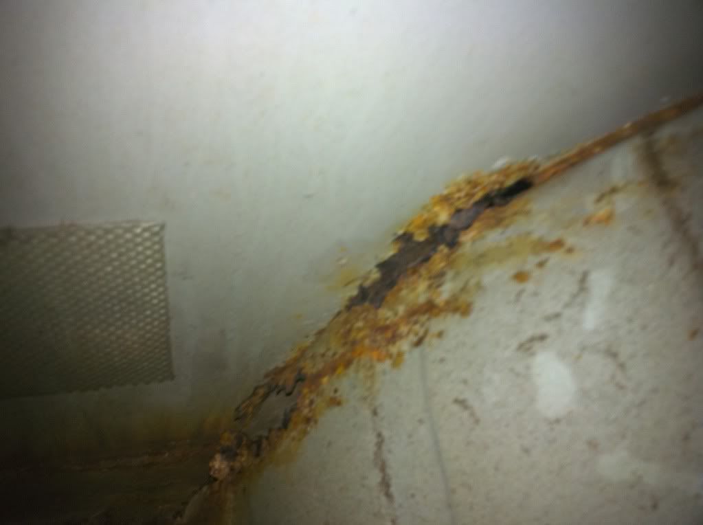
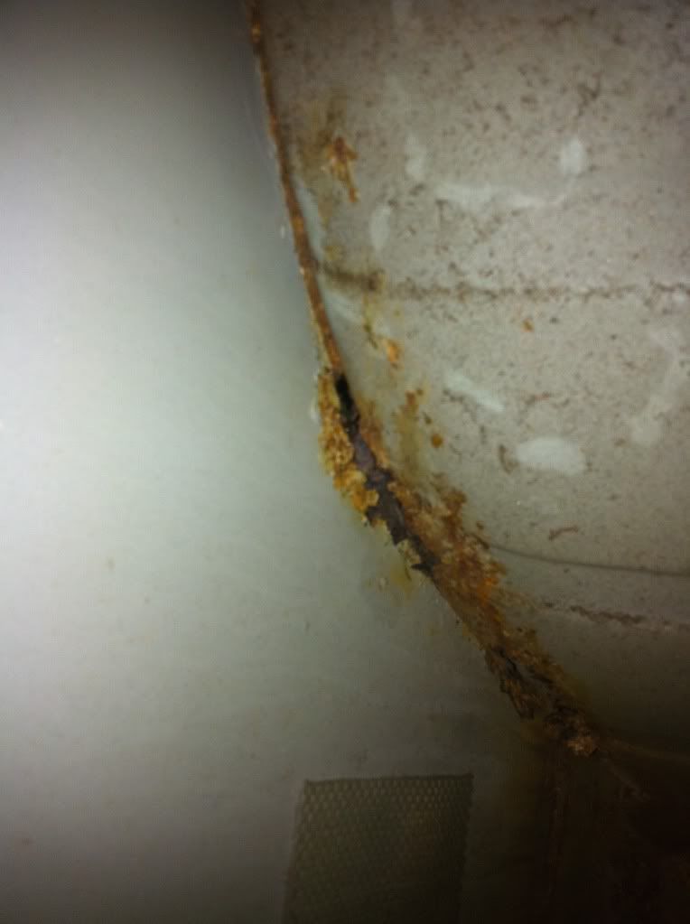
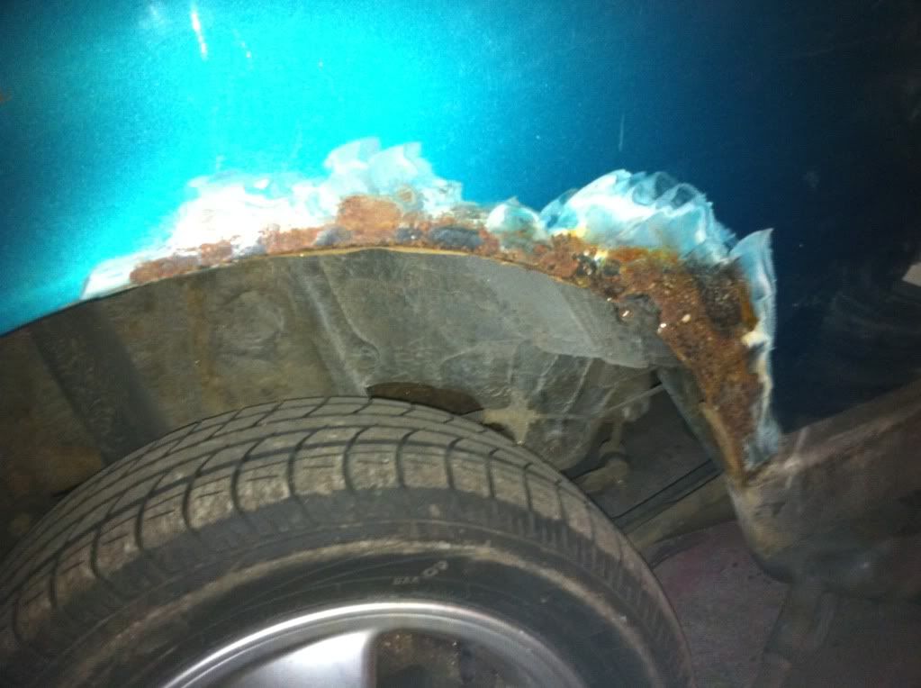
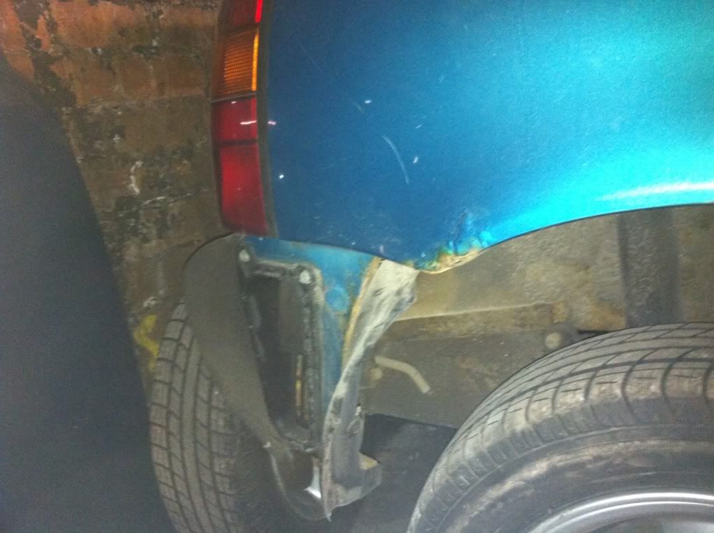
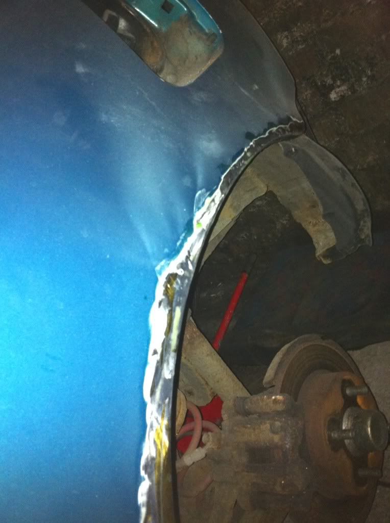
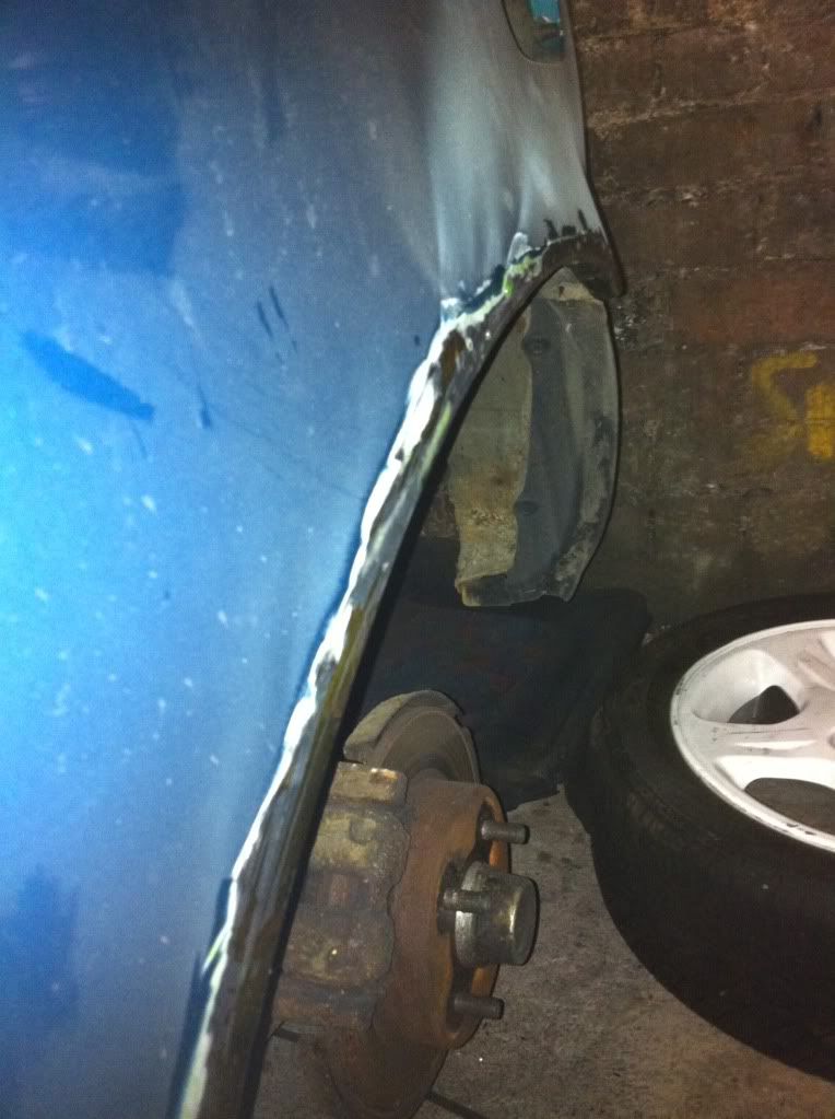
Both Rear innner and outer arches need attention aswell as one of the chassis legs and under one of the wing mirrors.

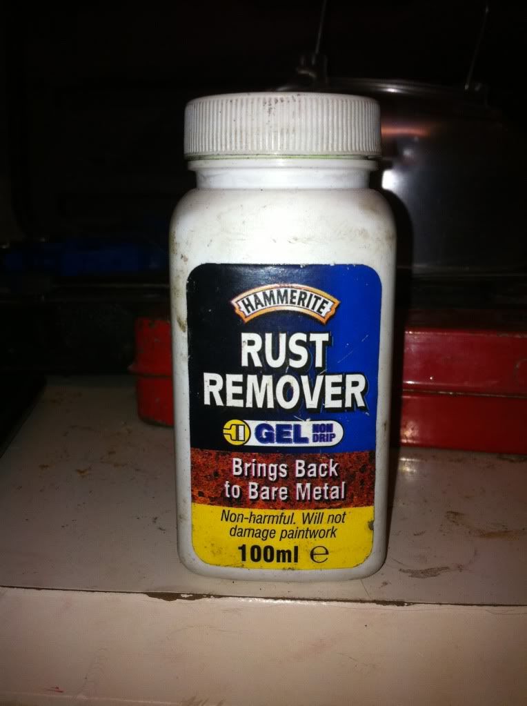
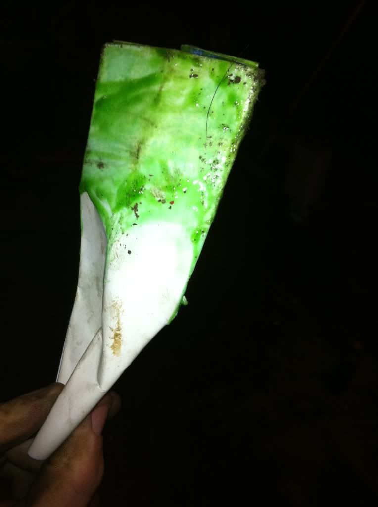
So i set to work with the grinder and flap wheel on removing all the rust. I started on one of the rear arches which wasnt that bad. Just alot of surface rust. So with that grinded down I Put on some Hammerite rust remover gel.

IMG_0632.jpg


And my paintbrush!

IMG_0633.jpg


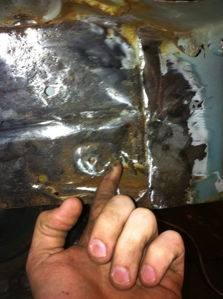
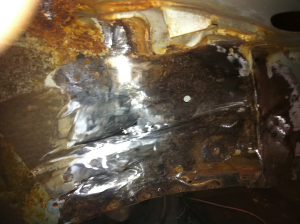
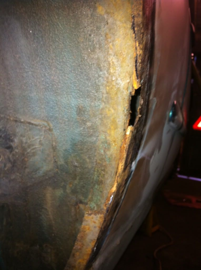
I then moved onto the front chassis leg which had a gaping hole. This needed welding... So grinder again to take back most of the rust for a plate to be welded over the whole.

IMG_0625.jpg


Rusty hole with the metal resembling "biscuit". It was very thin.

IMG_0624.jpg


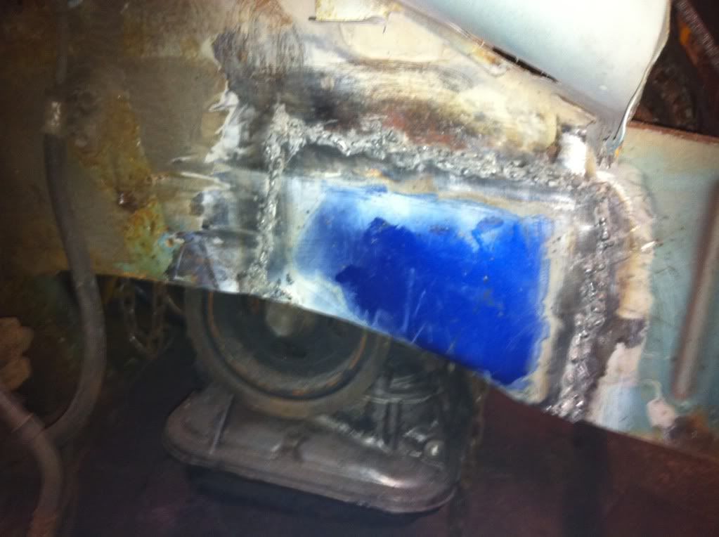
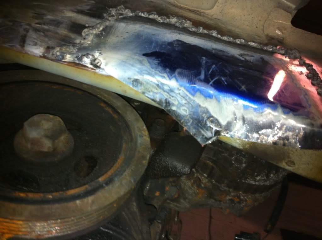
Once the Rust was grinded back, a template was made from the hole and a sheet of metal was cut from a spare wing we had lying around. Welder out and Ross welded the plate on. Yes the welder is sh*te, no comments on the seagull crap Liam!

IMG_0646.jpg


Theres still a bit left to do underneath, this will be done once the engine has been taken out again to have flywheel and clutch fitted.

IMG_0647.jpg


Just needs to be brought round and welded up.

And some previous welding we done on the arch in the engine bay looking at it from inside the wheel arch. Not pretty but strong :

IMG_0626.jpg


So with that done, more de-rusting on the door/wing mirror.

Rust grinded back, rust gel applied.

IMG_0627.jpg


Then I moved onto the other rear arch... big mistake.

Surface rust grinded back along the arch and the arch lip. We knew that there would
be welding needed here but after a bit more inspection it was revealed that alot more was involved. First look showed a small gap into the inner arch. Ok cool a little bit of welding needed.

IMG_0630.jpg

IMG_0631.jpg


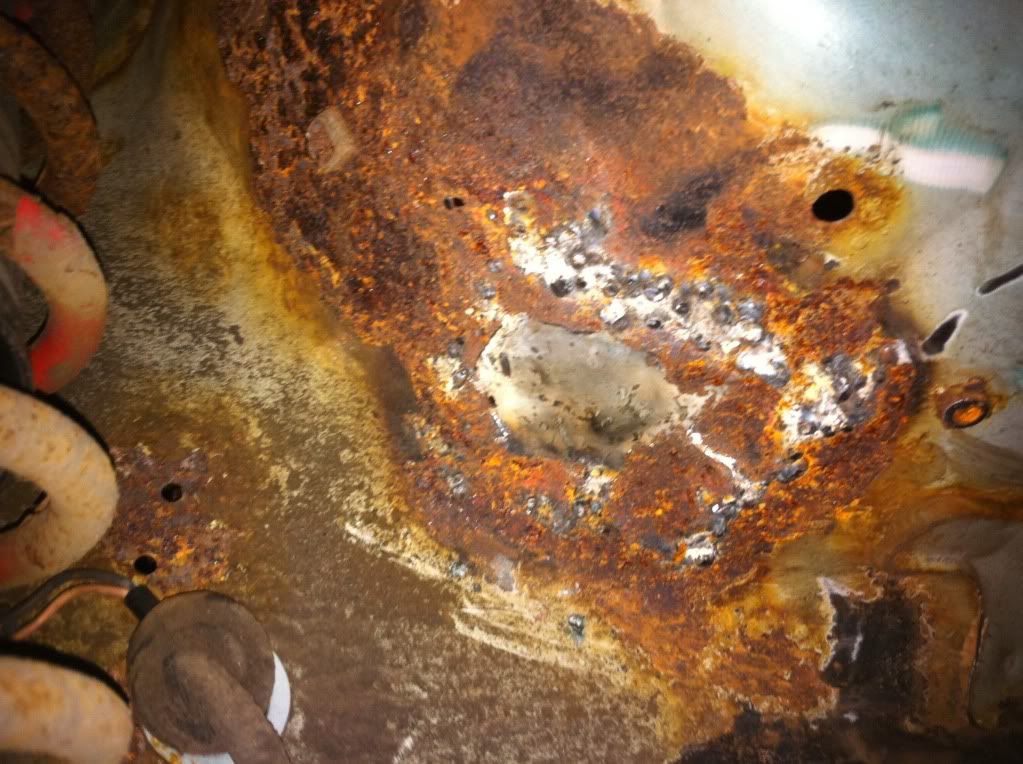
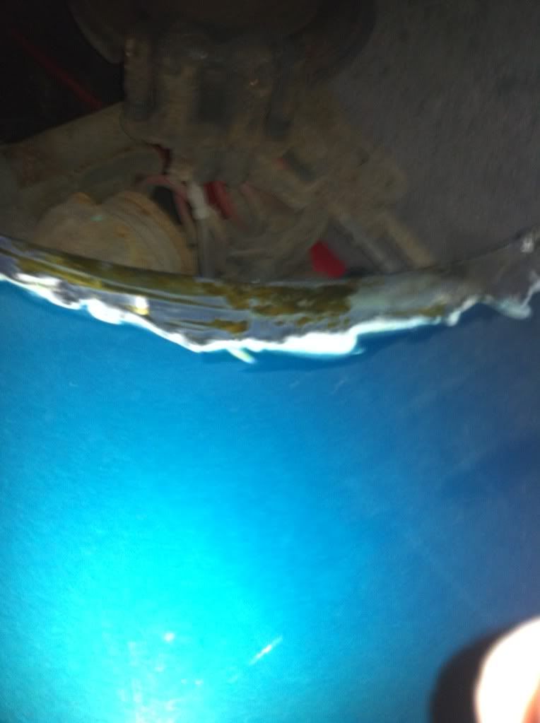
So after grinding back everything and poking the arch lip ( biscuit metal again) a larger hole was revealed (Thank you Rick...)

IMG_0645.jpg

IMG_0643.jpg

IMG_0641.jpg


So now two plates will need to be welded in to try and regain as good a shape as possible to original.

More pics of rust and rust removal!

IMG_0628.jpg

IMG_0629.jpg

IMG_0623.jpg

IMG_0622.jpg

IMG_0621.jpg


Thats all for the de-rusting just now. It feels good to kill the dreaded brown stuff.

All arches will be fillered up and sanded down then painted.

And on another note, all wiring is pretty much finished! Wires soldered up and heat shrinked. Just need to do the last few then it can all be tidied up.

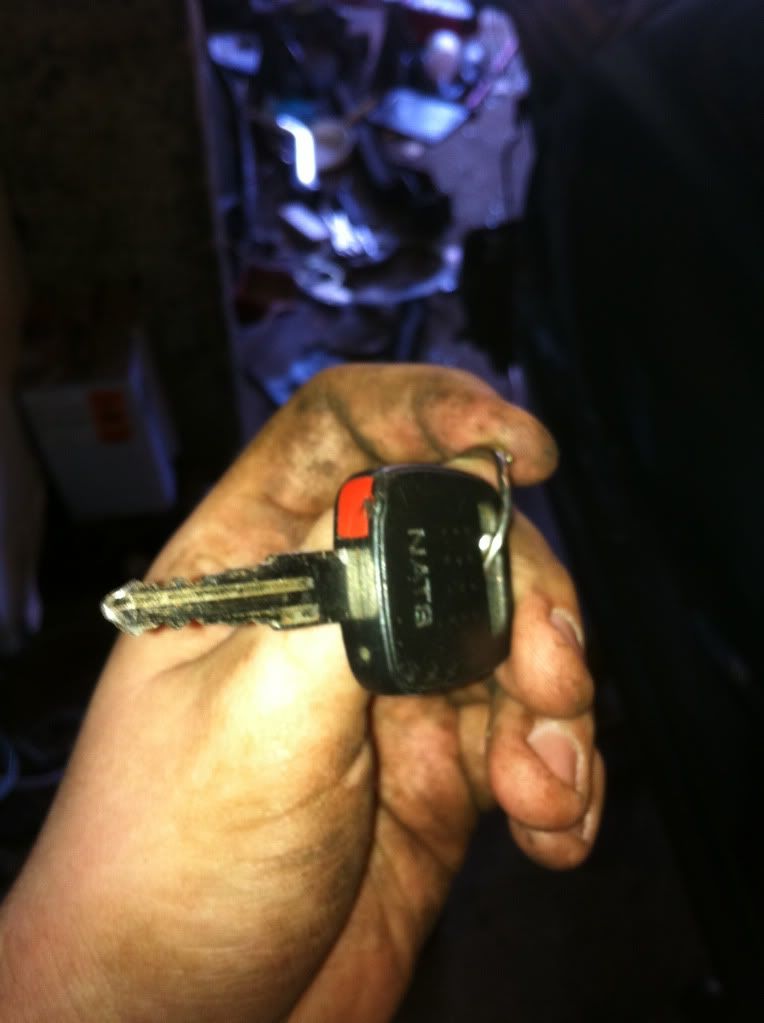
Also another piece of the puzzle is solved. We have sourced the necessary NATS stuff (ECU, keychips and NATS box) to get the engine running. Thank you Joe!

So we are currently on track for the 27th April Deadline of getting the engine started. Just need to get the NATS stuff, remove the engine, fit the engine loom, fit flywheel bolts, clutch, fill with oils, mount it back up and start it up!

Its also our 1 Year anniversary in the unit next week :happybday:
 
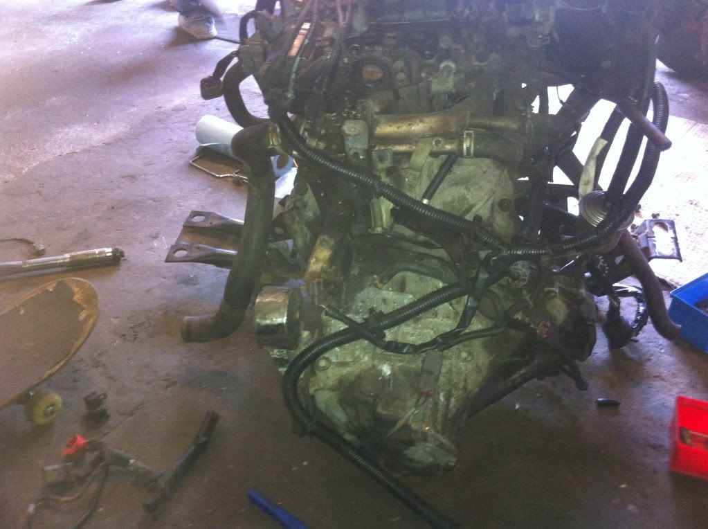
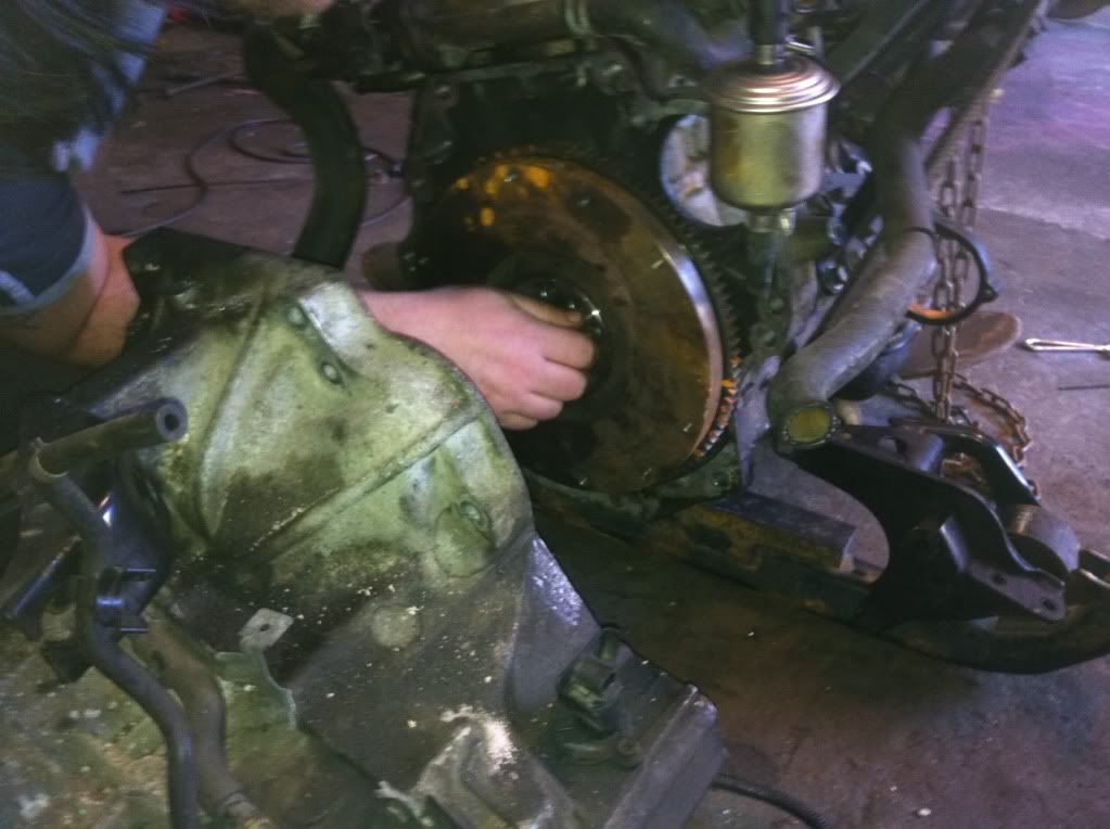
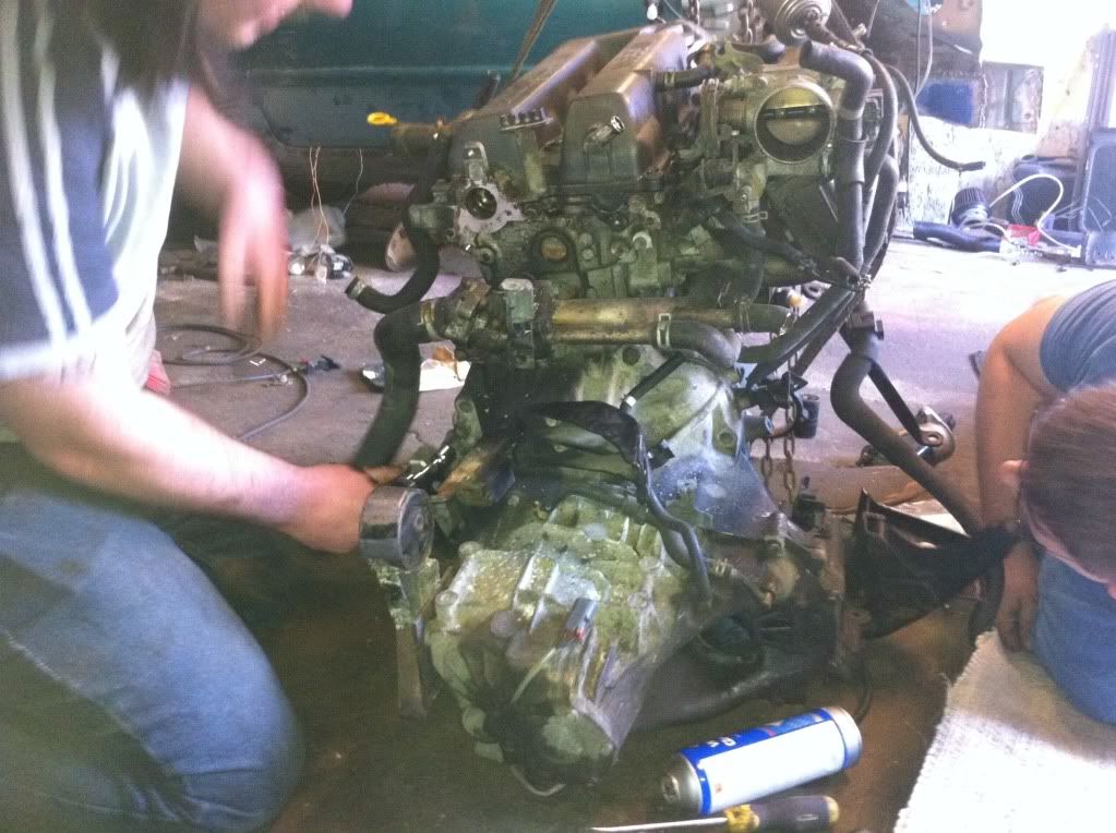
First off we took the engine back out the Micra to fit the 2 missing flywheel bolts, fit the clutch, make more modification to the crossbrace so that it bolts in perfectly to the Micra chassis. So engine out onto floor.

IMG_0666.jpg


Gearbox from the 2.0 was removed and so was the gearbox from the Micra engine as we needed the clips on the release bearing.

So Gearbox off, and flywheel goes to get fitted. Oops we are missing the spacer that goes on the flywheel. This coulda set us back weeks but fortunately I had one sitting in my drawer at home! So off home, grab the spacer and back the unit.

The main delay in having this put on was we were missing two of the bolts that were needed to bolt it to the crank. So it seems GA14 bolts are the same thread pitch but just a different head on the bolt. SR = 12 point whereas GA = 6 point.

Flywheel being fitted

IMG_0657.jpg


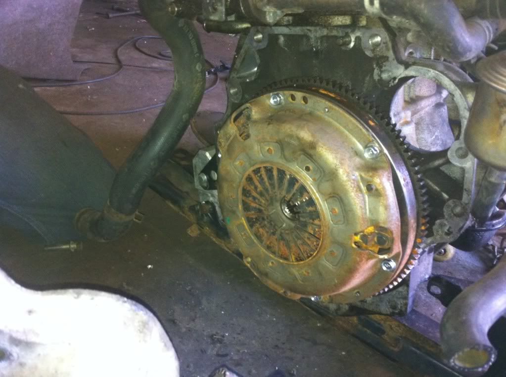
Then onto the clutch fitting. Once again we were lacking the correct bolts. So an order to G spec in the US got us a brand new set of clutch bolts. Delivery took a week or so.
Thank you to Phil/Happyharry for donating the clutch.

IMG_0658.jpg


Clutch taken from an SR16VE.

Clutch fitted :

IMG_0659.jpg


Gearbox then re-fitted :

IMG_0660.jpg


After this we then fitted the engine loom to the engine. We had to re-wire the injectors due to it being a phase 2 loom and a phase 1 engine where the injector plugs are different. So wires cut and replaced with the correct plugs then heat shrinked. Then NATS box was plugged in and the Micra keychip swapped for the Almera one.

Key chip fitted :

IMG_0662.jpg


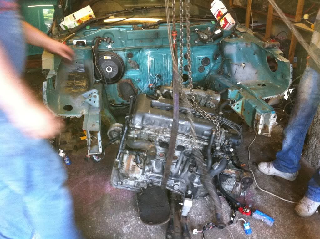
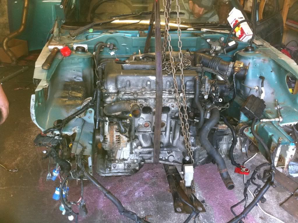
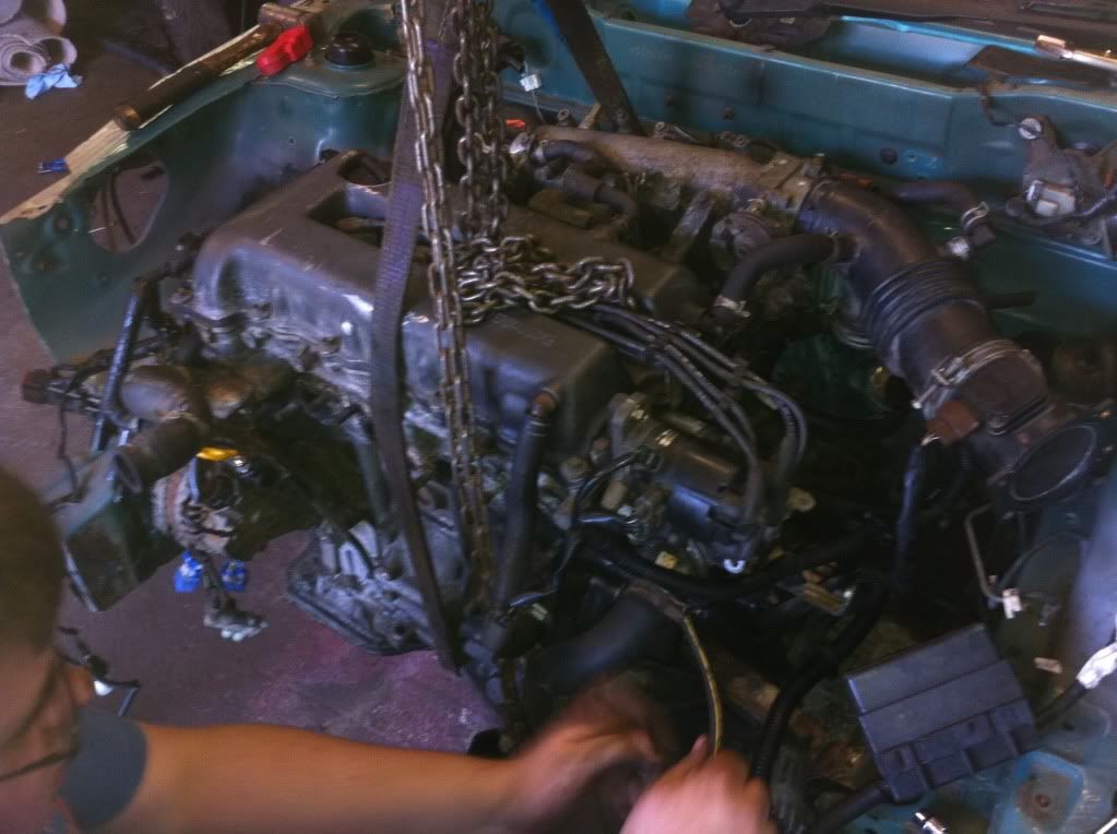
Engine then wheeled back into engine bay and lifted into position :

IMG_0667.jpg


Mounts bolted in :

IMG_0668.jpg


IMG_0669.jpg


Once that was done, the engine loom was fed through the firewall into the cabin. All plugs and fuseboxes were plugged in and a battery was fitted in place.

The engine was then filled up with oil. 3.5 litres. No oil in the gearbox yet due to no driveshafts.

[video=youtube;OrQfOYVijvw]http://www.youtube.com/watch?v=OrQfOYVijvw[/video]

It lives. First turn of the key aswell…Easy.

Unfortunately, as expected the wiring wasn’t totally correct for the fuel pump. For the fuel pump to prime and work before starting, the headlights must be switched on and left on. So some re-wiring needed there.

But the main thing is, its mounted on 3 mounts and it runs fine.

YAS.

Also a big thanks to Willie/Nistro for coming all the way from Aberdeen today to help us out.

Next job is the front crossmember.
 
Yeehaaaaa!

Seriously though guys, turn the thing off, as the gearbox bearings will be taking a beating without you having oil in it!
 
Back
Top Bottom